Less than fifty years ago the beam axle suspended on semi-elliptic springs was the norm at both ends of the automobile. There were a few exceptions. Zaire-Naudin used a sliding pillar independent suspension at the front as early as 1906 and a few years later the Morgan three-wheeler and the Lancia Lambda appeared with refined examples of the basic design.
Even so, these were regarded as rather expensive eccentricities and did little to convince the bulk of automobile manufacturers that the simple rigid front axle mounted on leaf springs, and the much heavier rear axle casing with similar springs, were not a final solution to the problem of springing.
All that was needed, or so it seemed, was a measure of refinement and a gradual reduction in the manufacturing costs. Despite this air of self-satisfaction, many experienced motorists knew that both front and rear axles could sometimes develop their own form of ‘shakes’.
At the front, it was called shimmy, and at the rear tramp. For good measure, some front axles were capable of both phenomena.
The driver could feel the onset of a shimmy when the steering wheel began to vibrate rapidly from side to side. This, precisely, was what was happening to the front wheels. Accessory manufacturers made steering dampers designed to reduce the amount of shimmy.
In racing and sports cars, the designer provided very stiff springs to reduce the angular deflection of the front axle, since this angular deflection of the axle is the source of shimmy.
With a beam axle, a tramp can occur at the front or rear. Even when shimmy is eliminated a beam axle can still develop a tramp, which is a transverse rocking action at spring frequency that can persist for many seconds.
The live rear axle
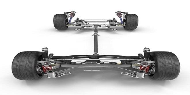
All pro automobile designers have now adopted independent suspension for the front wheels. A beam axle at the rear is 80 Conventional systems usually called a live rear axle when it also acts as the housing for the final drive unit and axle shafts.
The teen dead rear axles have been adopted to describe the use of a beam axle between the rear wheels on a front-wheel-drive car.
The live rear axle is relatively heavy in comparison with an independently suspended one. The outer casing is constructed from malleable castings and/or steel pressings and contains the final drive crown wheel and pinion, the differential casing and its gears, the half-shafts, and all the necessary bearings to support the moving parts.
The customary drum brakes, brake shoes, backplate, wheel hubs, wheels, and tires all contribute to a formidable unsprung mass.
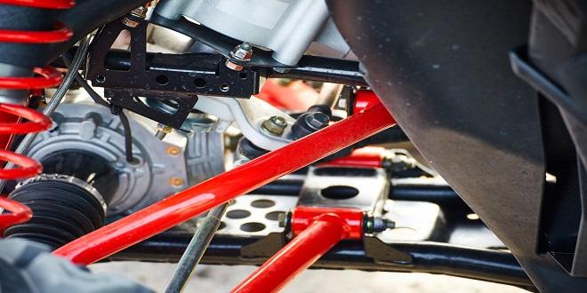
This system dispenses with the lateral location link .by arranging the ‘longitudinal’ upper links at an angle relative to the center line of the car.
Such a layout is not likely to give such accurate lateral location as that provided by a Watt’s linkage.
Last word
The only surviving example of this sliding pillar system is seen on the Morgan sports car. From the earliest designs dating back to 1910, the Morgan Motor Co. has gradually developed a well-engineered layout.
Single wheel movements in bump or rebound are vertical, with a small reduction in track, as shown by the broken line in the figure as the wheel rises.
When the car rolls, however, both wheels adopt new camber angles directly related to the roll angle. In the example shown with static camber angles of 2°, a role of 3° when cornering hard would give a camber of 50 on the outer wheel and lOon the inner.